|
Our Product Range
|
 |
 |
Home »
Info
Center » Valve Switching Positions
Valve Switching Positions
For each of the switching positions
provided by a valve, the graphic symbol shows a square, sometimes called a
box. This means the valve on the left provides two switching positions and
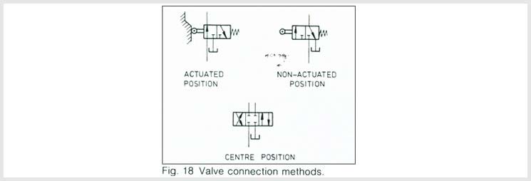
the valve on the right three. The non-actuated position of a valve is
assumed by its moving parts (valve mechanism) when the valve is not
connected, not pressurized, and not actuated. In most hydraulic control
circuits all valves are depicted in this non-actuated position, and by
convention two-position valve symbols should normally be connected on the
right-hand square .

Three-position valves should be connected to the center square, which again
depicts the valve's non-actuated position (sometimes also called the neutral
position). However, it is the practice of some circuit designers to draw
valves in circuit diagrams in their actuated or so-called initial position.
This position is assumed when the valve is installed in the machine and
levers, cams or machine parts are pressing onto the valve's operating
element, so that the valve's mechanism is no longer in the non-actuated
position. Since this is not a standard practice, it is imperative to state
on the circuit diagram that all valves are shown in their initial position.
Also, each of the valves which are actuated must be shown with a cam, and
all pressure lines are to be connected to the left-hand square .

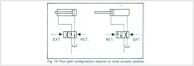
Two-position valves which are not spring biased and can freely assume both
switching positions (bi-stable), may be drawn in whatever flow-path
configuration demanded by the actuator position. But here again, the
pressure lines must be connected to the right-hand square.


